Radiance and Irradiance measurements
Radiance measurements are carried out to determine the amount of radiant intensity per unit projected area [W/m²/sr] and are measured using a lens system as optics to target at diffuse surfaces [e.g. OLED or display panels].
Irradiance defines the amount of radiant flux incident on an object’s surface, typically expressed in power per unit of surface [W/m²]. Typically, irradiance measurements are carried out with a spectrometer equipped with a cosine corrector with a predefined diffuse measurement surface. These devices are capable of showing the spectral power distribution, as well as showing parameter such as color, CCT, CRI, dominant & peak wavelength, PAR values, illuminance and luminous intensity. Irradiance measurements for large and high power light sources can also be carried out by means of a spectroradiometer connected to an integrating sphere setup.
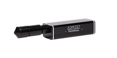
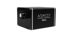
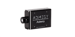
Admesy offers complete solutions to carry out irradiance measurements for various types of light sources like for example LED or incandescent lamps. The table below shows an overview of Admesy’s spectroradiometers suitable for radiance and irradiance measurements including their spectral ranges. More information about the measurement procedure can be found in the application guide.
| Neo | |
|---|---|
| Radiance [W/m²/sr] | Lens |
| Irradiance [W/m²] | Cosine corrector* |
| Radiant intensity [W/sr] | Cosine corrector* |
| Low luminance | yes |
*Instead of cosine correctors, integrating spheres can also be used to determine [spectral] irradiance and radiant intensity / illuminance and luminous intensity.
How are you measuring?
With fibers and other accessories even more type of measurements are possible. Often used accessories are integrating spheres, cuvettes for fluids, light sources or filter holders.
A cosine corrector collects the light from the half space under 180 degrees. A typical application is the illuminance measurement of a lighting situation.
Consumers are used to enjoy top-quality displays in their mobile phones, tablets, laptops and even cars. Emerging technologies such as lighting surfaces for office and home illumination are expected to look equally perfect. Both displays and luminous surfaces are the main application areas for imaging colorimeters.
Measuring the luminance or color values at a specific location of the device under test is a typical use case when measuring displays. It can, however, also be meaningful to assess reflected light.
Viewfinder Spectrometer

Standard lens 1.2° spot ⌀ 4.56 mm ‑ 6.71 m
Viewfinder Spectrometer

Close up lens 0.75° spot ⌀ 0.96 ‑ 1.47 mm
Colorimeter 2.1 mm

0.001 - 30 000 cd/m² (190 000 cd/m² in UHL mode)
Colorimeter 2.1 mm w/ pointer

0.001 - 30 000 cd/m² (190 000 cd/m² in UHL mode)
Colorimeter 5 mm

0.001 - 30 000 cd/m² (190 000 cd/m² in UHL mode)
Colorimeter 10 mm

0.001 - 30 000 cd/m² (190 000 cd/m² in UHL mode)
Colorimeter 10 mm wide-angle

0.0003 - 7 500 cd/m² (190 000 cd/m² in UHL mode)
Colorimeter 20 mm

0.0003 - 7 500 cd/m² (48 000 cd/m² in UHL mode)
Colorimeter 27 mm wide-angle

0.0001 - 2 800 cd/m² (20 000 cd/m² in UHL mode)
Spectrometer

VIS 380 - 780 nm
High-End Spectrometer

VIS 360 - 940 nm


